To understand vSAN component placement and sizing , we should be proficient in creating storage policy and understand the parameters you choose while creating a storage policy . I recommend you to read the vm-storage-policy guide before proceeding .
Please note the following Section “Understanding Component Placements” will not apply to vSAN Clusters running version 7 U1, as there are some changes for placements, which considers new space efficiency feature for slack-space. Please read the new blog for “Component-Placement-7U1 and above”.
Types of Objects seen in a vSAN environment
A VM can have five different types of objects on a vSAN datastore as follows, keeping in mind that each VM may have multiples of some of these objects associated with it:
-
VM home or “namespace directory”
-
A swap object (if the VM is powered on)
-
Virtual disks/VMDKs
-
Delta disks (each an object) created for snapshots
-
Snapshot memory (each an object) optionally created for snapshots
The VM namespace may need a little further explanation. All VMs files, excluding VMDKs, deltas (snapshots), memory (snapshots) and swap, reside in an area called the VM namespace on vSAN. The typical files found in the VM home namespace are the .vmx, the .log files, .vmdk descriptor files, and snapshot deltas descriptors files and everything else one would expect to find in a VM home directory.
Each storage object is deployed on vSAN as a RAID tree, and each leaf of the tree is said to be a component. For instance, if I choose to deploy a VMDK with a stripe width of 2, but did not wish to tolerate any failures (for whatever reason), a RAID-0 stripe would be configured across a minimum of two disks for this VMDK. The VMDK would be the object, and each of the stripes would be a component of that object.
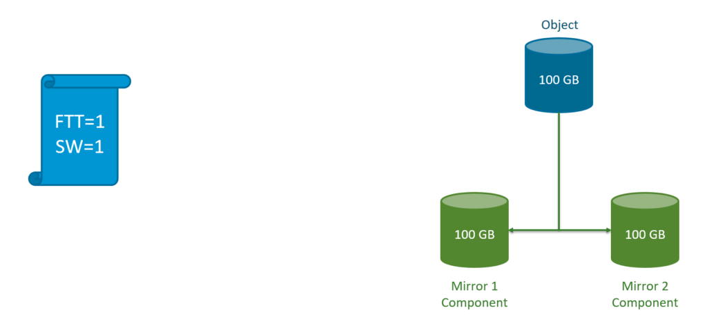
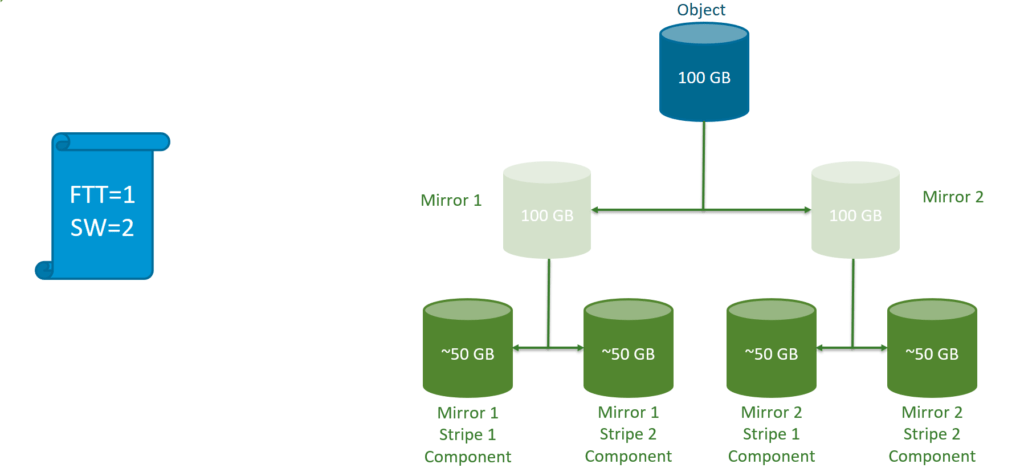
Similarly, if I specified that my VMDK should be able to tolerate at least one failure in the cluster (host, disk, or network), and left all the other policy settings at their defaults, a RAID-1 mirror of the VMDK object would be created with one replica component on one host and another replica component on another host in my vSAN cluster. Finally, if my policy included a requirement for both striping and availability, my striped components would be mirrored across hosts, giving me a RAID 0+1 configuration. This would result in four components making up my single object, two striped components in each replica.
Note that delta disks are created when a snapshot is taken of a VM. A delta disk inherits the same policy as the parent disk (stripe width, replicas, and so on).
The swap object is created only when the VM is powered on.
There is another component called the witness. The witness component is very important and special. Although it does not directly contribute toward VM storage, it is nonetheless an important component required to determine a quorum for a VM’s storage objects in the event of a failure in the cluster. We will return to the witness component shortly, but for the moment let’s concentrate on VM storage objects.
To Understand how to view component placements for a VM or an Object , see : https://virtuallysensei.com/understanding-vm-storage-policies/
Understanding Component placements
Now lets understand how the components are placed the way it is placed whenever you create a VM or a VMDK for a VM . Remember this is controlled and dictated by the policy defined for the VM or VMDK that you are about to create . Here is a small set of illustrations of different types of Object placement without considering witness objects , since we know by now that it is generally used as Quorum /Tie-breaker and this will be placed on of the hosts which should contain data or mirror components .
Glossary :
FTT = Failures to Tolerate ( generally host/disk/diskgroup )
SW = Stripe width (stripped component for an Object , note that if we dont have enough disks to satisfy the SW defined , vsan can still create two stripes on one disk within a Disk group)
The following Illustrations explain how components are placed with RAID-0 and RAID-1 as a part of default sets of VM storage policy which is applicable for both Hybrid and All-Flash setup .
- Policy of FTT= 0 and SW =1 created,
- Policy of FTT=1 and SW=1
FTT=2 and SW=1
FTT=1 and SW=2
FTT=2 and SW=3
FTT=1 and SW=1 , Object size =400GB (larger than 255GB) .
FTT=0 and SW=1 , Object size = 600GB (larger than 255GB) , here choosing sw=3 or sw=1 does not make a difference we will still create three components
What happens when we change the SW for an objects thru storage policy Ftt=1 and SW=2 to FTT=1 and SW=3 . For a brief period of time , double the storage capacity will be consumed by this object until new object/component creations complete , post which original components and objects are deleted .
Lets now see how components are placed with RAD5/6 erasure coding with space efficiency .
For RAID-5 Objects :
Limitations : FTT is fixed to 1 , Minimum hosts required is 3+1 (4 node cluster) , Only available for all-flash vSAN configurations
Benefits : Saves space compared to traditional RAID1/0 approach with the use of distributed parity blocks.
- FTT=1 , SW=1
FTT=1 , SW=2
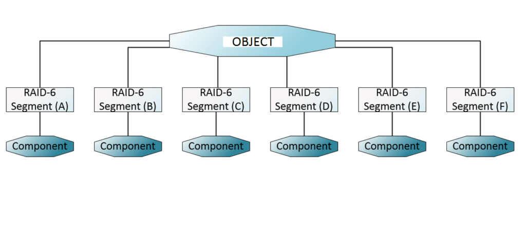
For RAID-6 Objects :
Limitations : FTT is fixed to 2 , Minimum hosts required is 4+2 (6 node cluster) , Only available for all-flash vSAN configurations
Benefits : Saves space compared to traditional RAID1/0 approach with the use of distributed parity blocks.
- FTT=2 , SW=1
FTT=2 , SW=2


